ACF is the abbreviation of anisotropic conductive film
With the continuous heating up of consumer electronic products, people are more fond of “thin, light and small” electronic products, and then pursue micro-component technology. COG technology is just one of these many technologies. COG is the abbreviation of “chip on glass” in English, that is, the IC is directly bonded to the LCD through ACF (anisotropic conductive film)
The development of IC is becoming more and more small pitch and small gap, and thus the requirements for COG equipment and COG technology are getting higher and higher. At the same time, other problems caused by this will also be exposed, so it also puts forward higher requirements for COG process technology. At the same time, higher requirements are put forward for ACF materials and testing equipment.
What is ACF(anisotropic conductive film)?
ACF can provide fine-pitch, high-reliability cold interconnects and is currently widely used in flat panel displays (FPDs) such as liquid crystal displays (LCDs). Among them, ACF has been industrialized in thin film transistor (TFT) liquid crystal display, outer lead bonding (OLB) interconnection of TFT liquid crystal display, and flip chip packaging (FCP), chip on film (COF), chip on glass (COG) and plastic LC interconnects are under development. One of the most widely used areas is COG. With the development of the entire industry, COG ACF is becoming more and more adaptable to small pitches and small areas.
The full name of ACF is Anisotropic Conductive Film, that is, anisotropic conductive adhesive. ACF is a material that can achieve conductive connection in a short time. SONY designed and sold the world’s first ACF in 1973. ACF is characterized by electrical conduction in the longitudinal force direction, that is, the Z direction, and has obvious high impedance characteristics in the transverse plane, that is, the X and Y planes. Its outstanding feature is that it can be pressed in a short time, with high reliability and good heat resistance. It can still maintain good reliability through the reflow oven. It is easy to connect fine-pitch lines and small terminals’ chips.
The main functions played by ACF: conduction, insulation, bonding:
COG ACF structure
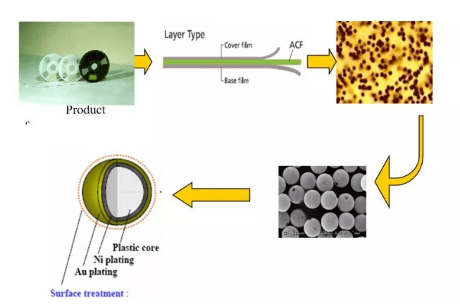
COG ACF is packaged in rolls, and the ACF used by COG mainly has a three-layer structure: Cover film, Base film, and ACF. Among them, the main specifications of ACF size and reel are as follows:
1.ACF length: 50m for general use. Other specifications include: 25m, 100m, 200m.
2.ACF width: The width that ACF can provide is 1.0~20mm. Now the most commonly used specifications of COG are: 1.5mm, 2.0mm, 2.5mm, 3.0mm, 3.5mm.
3.Reel Specifications:
Standard outer diameter: Φ 125mm (others may have Φ 95, 135, 145, 155, 230mm)
The standard inner diameter is: Φ 25.4mm (except that there may be Φ 18.5mm)
4.Conductive particle specifications:
The diameters of conductive particles mainly include: 3um, 3.5um, 4um, 5um, etc.
ACF glue layer structure
In the ACF layer structure, the two-layer cover film mainly plays a protective role, and the main structure is the ACF layer. The ACF layer includes resin glue, conductive particles and other additives, the proportion of which is mainly determined by the use and conditions of ACF.
1.resin adhesive
In addition to the functions of moisture resistance, adhesion, heat resistance and insulation, the resin adhesive is mainly used to fix the relative position of the electrodes between the IC chip and the substrate, and provide a certain pressing force to maintain the contact area between the electrodes and the conductive particles.
Resins are generally divided into two categories: thermoplastic resins and thermosetting resins. Thermoplastic materials have the advantages of low-temperature bonding, fast assembly and easy rework, but they also have disadvantages such as high thermal expansion and high moisture absorption. At the same time, they also deteriorate at high temperatures, which cannot meet the needs of reliability and reliability. Thermosetting resins, such as epoxy resins, have the advantages of high temperature stability, low thermal expansion, and low hygroscopicity, but their disadvantages are high processing temperature and difficult rework. High reliability makes them still the most widely used materials.
2.conductive particles
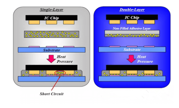
In terms of conductive particles, the anisotropic conductive characteristics mainly depend on the filling rate of the conductive particles. Although the conductivity of the anisotropic conductive adhesive will increase with the increase of the filling rate of the conductive particles, it will also increase the contact between the conductive particles and cause a short circuit. The probability.
In addition, the particle size distribution and distribution uniformity of conductive particles will affect the anisotropic conductive characteristics. Generally, conductive particles must have good particle size uniformity and roundness to ensure that the contact area between the electrode and the conductive particles is consistent, so as to maintain the same conductive resistance, and at the same time avoid part of the electrode from contacting the conductive particles, resulting in an open circuit. . The common particle size is between 3 and 5 μm. Too large conductive particles will reduce the number of particles in each electrode, and it is also easy to cause short circuit due to contact of conductive particles of adjacent electrodes; too small conductive particles are easy to form particle aggregation. The problem is that the particle distribution density is uneven.
At present, under the trend of high reliability and fine pitch, the anisotropic conductive adhesive used by COG, its conductive particles are mostly polymer plastic powder with nickel-plated gold on the surface, a plastic ball in the center, and nickel-gold plated outside. Its characteristic is that the plastic core is compressible, so the contact area between the electrode and the conductive particles can be increased, and the on-resistance can be reduced.
3.In order to prevent the lateral short circuit caused by ACF conductive particles, COG ACF now mostly adopts the double-layer structure of ACF layer to achieve this purpose
The structure of the ACF layer is shown below.
COG ACF conduction principle
The conductive particles are used to connect the electrodes between the IC chip and the substrate to make them conductive, and at the same time, the conduction and short circuit between two adjacent electrodes can be avoided, so as to achieve the purpose of conducting only in the Z-axis direction. as the follow picture shows:
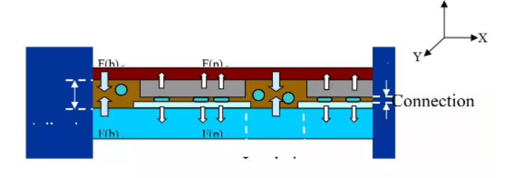
F(b) Force of conesion by ACF Binder
F(p) Force of elastic deformation by ACF partrefes
ACF hot pressing and COG process conditions
For ACF to work, it must go through hot pressing, that is, through the three necessary conditions of temperature, time and pressure, the ACF glue will be cured, and the conductive particles will explode to achieve the conduction effect, so as to achieve the three functions of ACF: bonding, insulation and conduction . For each type of ACF, there are its material characteristics, so there are certain differences in the requirements for conditions. So how to obtain suitable process conditions according to different materials is very important.
Temperature
Temperature is a necessary condition for ACF to function, and whether the temperature is appropriate directly affects the bonding effect and product reliability. Its impact mainly includes the following aspects:
1.ACF curing rate 2. IC bonding reliability 3. Blast effect of conductive particles
ACF requirements for temperature curve:
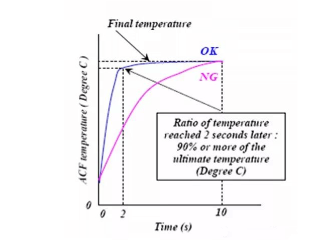
The temperature curve refers to the curve of the temperature changing with time during the ACF hot pressing process. The curing process of ACF resin glue is mainly the qualitative change process of the glue material. First, the glue melts and flows at high temperature, and this step is completed in a very short time. Immediately, the adhesive changes at high temperature – curing. In order to ensure the effective curing of ACF, special requirements are put forward for the ACF curing temperature curve – 90% of the target curing temperature must be reached within the first 2 seconds. As shown below.
ACF’s requirements on temperature and curing rate:
The above temperature curve is mainly the requirement for the heating rate, while another requirement for the temperature of ACF is the requirement for the final bonding temperature. Only when the temperature reaches a certain height, the ACF will solidify, so the determination of the main pressure temperature must reach the curing temperature of the ACF adhesive. This temperature will vary with different materials. But judging from the current use of ACF models, generally >180°C is required. That is, only when this temperature is reached, ACF can be effectively cured.
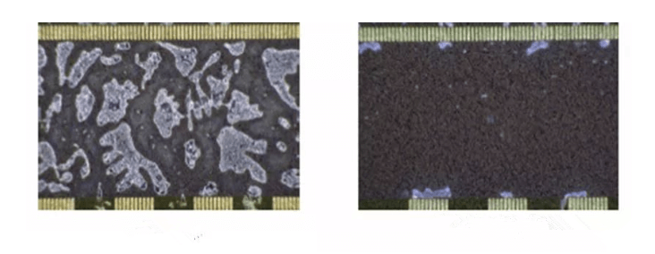
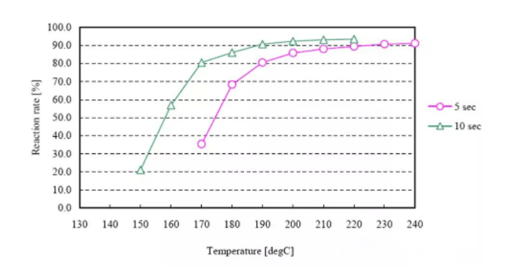
Another problem with ACF in achieving effectiveness is cure rate. At the same time, the biggest factor affecting the curing rate is temperature. It includes both the heating rate and the final curing temperature. The relationship between curing rate and temperature can be summarized as follows: at a certain heating rate, the higher the curing temperature, the higher the curing rate, as shown in Figure 7. In general, in order to ensure the reliability of IC connection, the curing rate of ACF needs to reach more than 70%. If the curing rate of ACF is insufficient, it will cause the following effects: 1. The bonding reliability of IC and LCD is reduced, and the IC is prone to peeling off; 2. Products with low curing rate are prone to form pressure bubbles, which will affect the reliability of IC electrical conduction; 3. The curing rate of ACF is low, and it is easy to cause ACF to be heated to form bubbles between IC and ITO during the FOG process or welding process.
Other temperature requirements of COG ACF: ACF application and IC pre-pressing temperature are generally 40~80℃. The maximum temperature cannot exceed 90°C, because after 90°C, the properties of ACF will change and start to solidify, which will affect the bonding effect of the main pressure.
TIME
In the COG process, ACF has three process requirements for time: ACF application, IC pre-pressing, and IC main pressing. Among them, ACF application and preloading time mainly consider the actual effect and efficiency. Generally between 1~3s. However, with the improvement of the operating speed of COG equipment and the improvement of ACF performance.
PRESSURE
ACF conduction is to achieve the purpose of electrical conduction between IC and ITO through conductive particles. But what kind of conductive particles are effective after bonding?
As mentioned above, the conductive particles are mainly gold-plated plastic balls, and the conduction function is mainly the metal layer plated on the outside of the plastic balls.
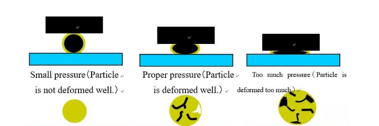
Effective conduction can only be achieved when conductive particles are blasted under force.
On-resistance: The connection resistance between IC and ITO can reflect the effectiveness of particle conduction. Under the same conditions, the smaller the on-resistance, the higher the effectiveness of the particles. COG engineering requires connection resistance <5Ω. Z-direction deformation after hot pressing.
ACF conductive particles are deformed after being heated and pressed in the Z direction. Taking particles with a diameter of 4um as an example, as shown in Figure 9 below, when the size of the particles in the Z direction is compressed to about 2um, the best conduction effect can be achieved.